
On a phone, pinch to zoom or turn the phone sideways.
Size TS 80
TS 80 – TS 031 444 worm gearbox
203 Nmmax. output torque M2 (SF = 1)
a = 80 mmcentre distance of the gear set
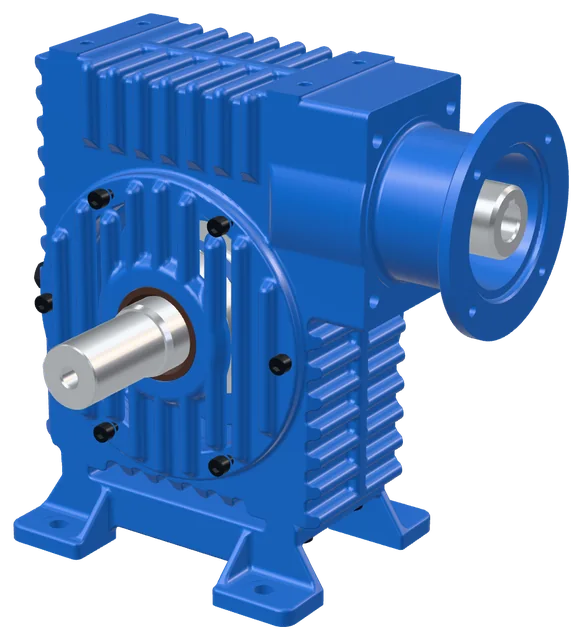
Gear ratios u10 – 80
Output speed n2 at 1 40016.4 – 141 min⁻¹
Max. input power P1 at 1 4001.89 kW
IEC motor, B14 flange80 · 90
Max. Fr / Fa at n2 < 104 100 / 2 400 N
Weight type S20.7 kg
Ratings and torquesSF = 1 · types S and E
| n1 = 1 400 min−1 | n1 = 900 min−1 | n1 = 700 min−1 | |||||||||
|---|---|---|---|---|---|---|---|---|---|---|---|
| u | usk | n2rpm | P1kW | M2Nm | n2rpm | P1kW | M2Nm | n2rpm | P1kW | M2Nm | MotorIEC B14 |
| 10 | 10 | 141 | 1.89 | 111.3 | 93 | 1.55 | 135.3 | 68.5 | 1.26 | 147.5 | 90 |
| 16 | 16 | 88.1 | 1.6 | 144.3 | 58.1 | 1.31 | 172 | 42.8 | 1.07 | 187.7 | 90 |
| 20 | 20 | 70.5 | 1.28 | 138.3 | 46.5 | 1.04 | 164.3 | 34.2 | 0.83 | 175.1 | 90 |
| 25 | 25.5 | 55.3 | 0.97 | 129.9 | 36.9 | 0.79 | 150.8 | 27.6 | 0.68 | 168.5 | 90 |
| 31.5 | 32 | 43.1 | 0.82 | 132.2 | 29.4 | 0.68 | 152.4 | 22 | 0.7 | 203.2 | 80 · 90 |
| 40 | 40 | 34.5 | 0.82 | 156 | 23.5 | 0.69 | 183.7 | 17.6 | 0.55 | 188 | 80 · 90 |
| 50 | 51 | 27 | 0.64 | 144.4 | 17.8 | 0.54 | 177 | 13.8 | 0.43 | 172.2 | 80 · 90 |
| 63 | 63 | 21.9 | 0.49 | 125.8 | 14.4 | 0.42 | 149.7 | 11.2 | 0.35 | 155.2 | 80 · 90 |
| 80 | 84 | 16.4 | 0.47 | 152.4 | 10.8 | 0.39 | 175.1 | 8.2 | 0.32 | 182.6 | 80 · 90 |
u – nominal ratio, usk – actual ratio, P1 – input power at the input shaft, M2 – torque at the output shaft. Motor – IEC frame sizes that can be fitted at the given ratio (type E).
Permissible overhung loads on the output shaftmounting 1, guide values
| n2 [min⁻¹] | < 10 | 10 – 25 | 25 – 50 | 50 – 75 | 75 – 100 | 100 – 170 | > 170 |
|---|---|---|---|---|---|---|---|
| Fr [N] | 4 100 | 4 100 | 3 700 | 3 000 | 2 500 | 2 100 | 2 000 |
| Fa [N] | 2 400 | 2 400 | 2 100 | 1 800 | 1 500 | 1 000 | 1 000 |
Send an enquiry for this item
Tell us the size, ratio, type, mounting, mounting position and quantity – we will prepare a quotation or help you choose.